- EasySpin
- Documentation
- Publications
- Website
- Academy
- Forum

Digital up- or downconversion.
[tOut,signalOut] = rfmixer(tIn,signalIn,mwFreq,type)
[tOut,signalOut] = rfmixer(tIn,signalIn,mwFreq,type,Opt)
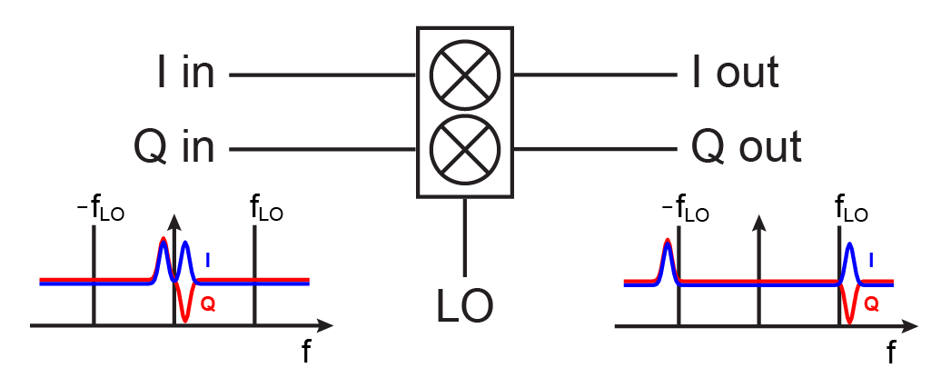
This function mixes the input signal (signalIn as a function of the time axis tIn in microseconds) with the LO frequency specified in the field mwFreq. Depending on the mixer type is specified in type, the function acts as a double-sideband (DSB) mixer, single-sideband (SSB) mixer or performs IQ modulation, demodulation or frequency shifting.
The output contains the time axis data in tOut (in microseconds) and the output signal in signalOut.
For up- or downconversion with a digital double-sideband (DSB) mixer, single-sideband (SSB) mixer or IQ modulation, only the in-phase component of the output is returned.
For IQ demodulation or frequency shift, the in-phase and quadrature parts of the up- or downconverted signal are contained in the real and imaginary part of signalOut.
Resampling of the input signal before up/downconversion can be performed by specifying a new sampling time step in Opt.dt. If no time step is given, the time step for the output signal is computed based on the maximum frequency of the signal.
If you don't request any output, rfmixer plots the up/downconverted signal.
The possible input arguments to the function are:
tInsignalInsignalIn for IQ modulation or IQ frequency shift.
mwFreq'IQshift' option, the sign indicating the direction of the frequency shift needs to be included.
type'DSB': double-sideband mixer
'USB': single-sideband mixer, upper sideband selected
'LSB': single-sideband mixer, lower sideband selected
'IQmod': IQ modulator, IQ mixer operation with I and Q inputs and real signal output
'IQdemod': IQ demodulator, IQ mixer operation with real signal input and I and Q outputs
'IQshift': IQ frequency shifter, the center frequency of the IQ input signal is shifted (signal output of an IQ mixer before the power combiner)
Opt (optional)
Opt is a structure containing different options for the digital up/downconversion. The available fields are listed below.
dt1/(2*Opt.OverSampleFactor*maxfreq).
OverSampleFactorInterpolationMethodinterp1 (default = 'spline').
BandwidthThresholdHilbertThresholdNoiseCutoffThresholdThe digital up/downconversion is performed as
![[eqn]](eqn/rfmixer1.png)
For single-sideband up/downconversion and IQ demodulation, the quadrature signal Q is determined from the real input signal I by Hilbert transformation. The Hilbert transform of I corresponds to Q only if the Fourier transforms of the amplitude and phase contributions to I do not overlap (Bedrosian's product theorem, see Boashash, B., Estimating and interpreting the instantaneous frequency of a signal. I. Fundamentals. Proc. IEEE 80, 520 (1992), DOI: 10.1109/5.135376). rfmixer checks for validity of this assumption and returns an error if it is not satisfied. In some cases, noise contributions to the signal lead to increased overlap. The calculation can still be performed if Opt.HilbertThreshold is increased.
The different options available in rfmixer are listed below with schematic block diagrams of the corresponding types of mixers and a simple example of operation.
'DSB')

'LSB')

'USB')

'IQmod')

'IQdemod')

'IQshift')
